Jfactory Presents…
Blender Hillshading
Prior Steps
Steps we already did:
- Download dem.tif
- Reproject into 102445
- Stretch to 65535
- Save as UInt16 (Unsigned integer 16-bit) tiff
Extraction
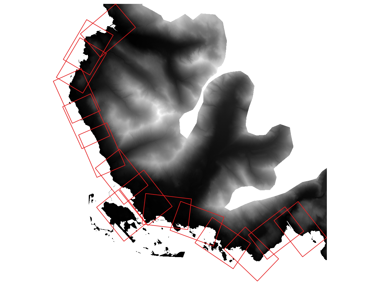
Overall view showing viewports in red
The red rectangles represent a sheet of Arch D paper sized at a scale of 1:200. We'll call these viewports.
For each drawing, we want to prepare shadows with the sunlight always shining from the upper-left. There is a sort of optical illusion if the shadows come from a different angle because our brains have been conditioned to the standard map angle for hillshading at 315°.
I use a query filter on the viewports layer. Each feature has a "dwg_name" attribute associated with it. If we isolate one feature, we can extract the dem.tif easily by using its extents.
The first page is the only one with its orientation so we only need to isolate just the one with "dwg_name" = "1". We will enter this in a query filter.
Right-click the viewports layer and click Properties. You can also just double-click the layer.
Choose Source tab on the left. In the lower-left click 'Query builder' and enter "dwg_name" = "1"
In QGIS, under Raster find Extraction > Clip Raster by Extent. Then after Clipping extent find the dropdown arrow ▼ and Calculate from Layer and choose your viewports layer.
Scroll down and choose to save your file. Hit save and if you're on a Mac a funny thing might happen (a bug, perhaps?). The Raster Extraction window will disappear almost making you feel like you finished. But you have to find the window. Hit 'run' on it and then you know you've finished.
Extractions continued…
Subsequent pages share orientations so we can simply extract for the pages that share them. A more technical query feature will help us.
"dwg_name" IN ('2', '3')Now it will show just those two pages. Run through the extraction process again and repeat these steps for subsequent viewports. I have been putting the dwg_names covered in the filename so as to not get mixed up.
Blender Time
Now we open our extracted .tif files in Blender.
- select and delete default cube
- shift + a and add image as plane
- alt + r to clear the rotation on the plane
- scale the plane to match the scale of the image. I prefer 10% size.
- type n to reveal side panel
- make sure item tab is selected
- under dimensions put in x and y values
- apply scale with ctrl + a
The order of the next steps isn't important
Render Properties 📷
- in the Properties panel find the Render properties
- change the Render Engine to Cycles
- change the Feature Set to Experimental
- optional: change the Device to GPU
Output Properties 🖨️
- find the Output Properties tab in the Properties panel
- set the resolution to match the source image
- change the format of the Output to tiff
Subdivision Surface Modifier 🔧
- in the Properties panel select the Modifiers tab
- select Add Modifier and choose Generate > Subdivision Surface
- change it from Catmull-Clark to Simple
- check 'Adaptive Subdivision'
Shader Editor
- in the very top-left is a button to select the Editor Type which is the window's view and it's currently set to 3D Viewport. change it to Shader Editor
- separate image texture node from Principle BSDF shader
- optional: change image texture 'linear' to 'smart' and 'clip' to 'repeat'
- shift + a to add Vector > Displacement node
- connect image color to displacement height
- connect displacement to Material Output node's displacement
- change Scale to 1200
- select Displacement node and type n to open the side panel
- select the Options tab and select the ▼ Settings dropdown
- Change Displacement to Displacement Only
Camera 🎥
- select the camera
- alt + r to clear rotation
- alt + g to clear location
- move camera up 100m or something
- in the Properties Panel find the Data Properties that has a Film Camera icon
- change lens type from Perspective to Orthographic
- change the orthographic scale to match the longest dimension of the plane
- change the Clip End to 1000m
Light 💡 Pt 1
Optional: change our model's already existing light or add a new one. Light options are infinite. The following are one man's preferences:
- click our Light 💡 in the Outliner
- in the Properties change it from Point to Sun
- change the Strength to 3.5 W
- leave angle at 11.4 this adjusts hard or soft shadows
- find the yellow box icon for Object Properties change
Rotation to the following:
- X: 0°
- Y: 45°
- Z: 135°
The Rotation Math was simple enough for the light. Instead of 0° starting at North like in Map Math, Blender Rotation values begin due East or 90° and the positive direction runs counter-clockwise. So, 135° in Blender = 315° Azimuth (technical name for angle of the sun).
Because the Viewport rotation will add additional math for our sun angle we will continue this in Light 💡 Pt 2.
Viewport
Let's add a camera for the viewport
- shift + a and select Camera
- let's first set the scale in the
- in the Object Properties change the name from Camera.001 to Viewport
- press alt + r to remove rotation
- move it up 100m or something
- in the Output Properties change the